An Unconventional Alarm Clock Goes Autonomous: Pt 2
Old parts, a leaning prototype, and an alarm clock with a new job: dealing with my laziness.
An Attempt at an Abstract
A brief disclaimer: This is a hefty technical article. If you just want to watch the demo and get the short version of what I built and how it came together, skip directly to Section V. I’ll try not to take it personally.
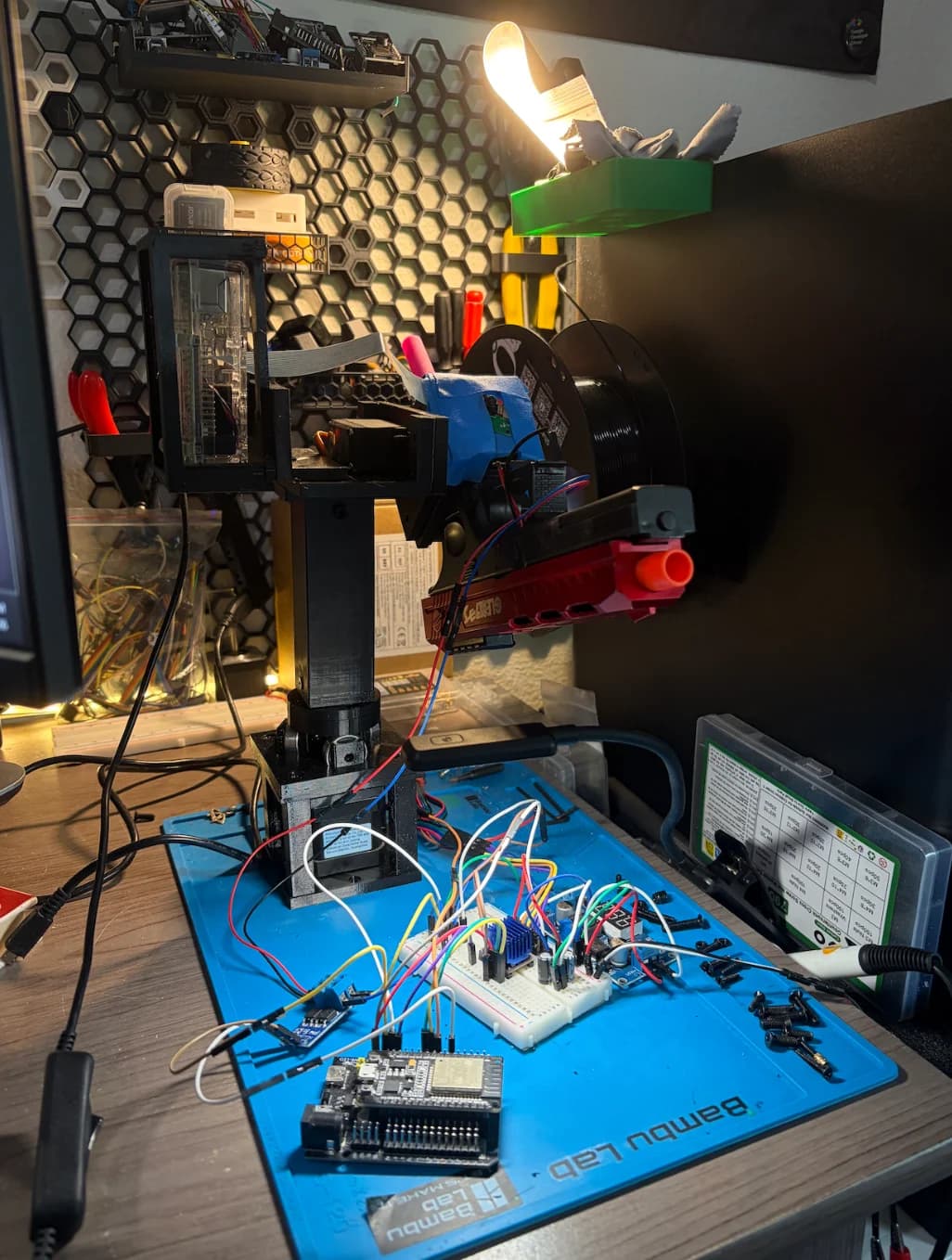
I think I can successfully say that I have crossed the line.
Which line? Well, if that question doesn’t make sense, I recommend reading Part One. It explains why I built an alarm clock unreasonable enough to require a sequel. So start there.
Section I identifies the parts, tools, and source files. Sections II through IV follow the machine from mechanical design and physics through electronics and software.
With the context established, we can begin at the genesis: a pile of parts on my desk.
I. Assembling Frankenstein
I think every unreasonable machine begins with a surprisingly reasonable parts list. Individually, these were mostly leftovers and somewhat questionable online purchases.
Below are the principal parts that made this possible. The open-source GitHub repository currently contains the mechanical designs and hardware documentation. The firmware and tracking software described here are not yet included in the public release.
By no means am I an open-source maintainer. If something in the repository looks wrong, please open an issue or send me a message :)
II. The physics
Physical reality has veto power
The planetary gearbox from Part One spent the summer collecting dust while I collected twenty-seven credits like Thanos collecting Infinity Stones. But when classes ended, I picked it up and rotated the plastic planets around the sun gear. The same neurons responsible for Part One began firing again. Now I wanted to build another alarm clock, one to combat an even bigger issue than waking up: my laziness.
Fall classes began in seven days. Seven days of freedom. Naturally, I converted them into another deadline.
I reopened the disorganized Fusion folder from Part One, swiftly designing an ugly-looking hexagonal output with a matching socket beneath the platform. I will admit, I spent more time choosing between STL and 3MF than evaluating whether the assembly could even support itself. I wanted the damn thing finished.
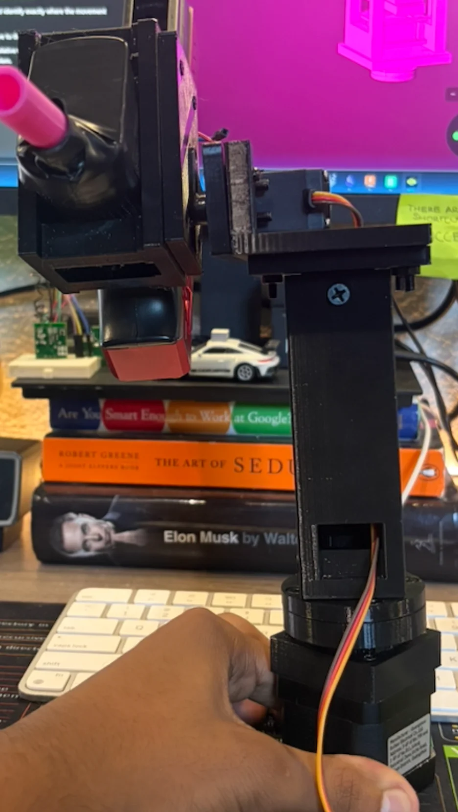
After some whirs and whizzes in the printer, I took it out and got to assembly. But after installing the final heat-set inserts, it kind of looked like the Leaning Tower of Pisa. Physics had been omitted from the model, and considering it was my major, I figured it was time to consult it.
A statics class I never took
Hopefully, I can write this section with a bit of brevity. From here, the physics is pretty fast-forwarded.
Problem one: the entire machine
The blaster, Pi, servo, and printed parts did not distribute their weight particularly democratically. To understand if the whole machine would tip, I had to include everything supported by its base, including the NEMA motor and its printed supports.
In this simplified side-view model, each component had a mass and a signed horizontal distance from the midpoint between the supports. Taking the right side as positive, its weight produced a tipping moment:
Here, is the acceleration due to gravity. Rather than keep describing every weight separately, I could represent their combined effect as the total weight, acting through the center of mass:
This gave me a position, not another weight. Multiplying that position by the complete supported machine’s weight gave its gravitational tipping moment about the same reference:
The NEMA’s centered mass brought the combined center of mass closer to the middle. It helped stabilize the base. It did not relocate the upper assembly’s own center of mass or remove its offset load at the gearbox connection.
If you read Part One, you already know that I do not particularly enjoy CAD. Rather than redesigning the upper assembly, I tried the simplest option I could think of: printing a wider box around the NEMA.
For this static model of a level, unanchored base under gravity alone, let be the distance between the supporting sides. To retain a margin against tipping, the complete machine’s center of mass had to project between them:
The box widened that footprint, but without relocating the upper assembly. The added mass could also alter the combined center of mass, but widening the support was the whole point.
The desk supplied upward reactions, and . Together, they supported the weight and balanced its tipping moment:
The more heavily loaded side carried more of the weight. The wider frame gave those unequal reactions more leverage to keep Frankenstein upright.
Problem two: the gearbox output
Yeah, so the solution in the previous section didn’t solve everything. It was clearly still leaning.
After extensive unscrewing, the remaining angle became easier to locate. The real tilt seemed concentrated around the gearbox’s output connection. Just appearing straight didn't imply the tower was unstressed. I learned that it just meant the obvious movement was occurring elsewhere.
I guess it was a local problem. I considered only the components carried by that connection, not the motor/base beneath it.
I’ll call the magnitude of their tipping moment .
I added some leftover skateboard bearings to support the output. Just like that, one failed project had contributed something useful to another.
A simplified way to describe resistance to rocking was an idealized force couple: two equal and opposite forces whose lines of action are separated by a perpendicular distance . Using force and moment magnitudes:
Therefore:
Bear in mind, this is a simplified explanation (not a measured load calculation for each bearing). The actual reactions depended on the bearing arrangement, supported weight, and remaining play.
While the bearings had not rebalanced the upper assembly, or even eliminated every loose fit, they had improved the support.
So the TL;DR is quite simple here. The box now resists the whole machine tipping. The bearings resist rocking at the output. It was the same statics lesson twice, yet at differing scales.
III. The electronics
One supply, two voltages
Unlike the physics, the electronics were definitely a bit less theological, in some senses.
I used an adjustable 3–24 V, 3 A DC supply to power the actuators. I set it to roughly 12 V and split the output into two branches:
12 V supply
├── 12 V → DRV8825 → NEMA 17
└── LM2596 buck converter → 5–6 V
    ├── tilt servo
    └── XY-MOS → blaster motor
The Pi 4 retained its own power adapter. USB powered the ESP32, which supplied only control signals: STEP and DIR to the DRV8825, PWM to the servo, and a logic signal to the XY-MOS. The relevant controller and driver grounds shared a common reference so the control signals had the same reference point.
Anyway, most of the trouble came from the DRV8825.
As I learned, stepper coils are inductive. Changing their current involves an inductor voltage:
Fortunately, I also happened to be lacking one appropriately rated capacitor. I had two 450 µF, 10 V electrolytic capacitors, so I wired them in series: approximately 225 µF of effective capacitance, but not a guaranteed safe 20 V rating. Voltage sharing can be uneven. The prototype ran, but I would not recommend reproducing that compromise.
I also added a massive heatsink to the driver. That big thing helped with the heat, but it didn’t exactly solve the overvoltage problem.
After that, the DRV8825 was relatively cooperative. Especially compared with my attempts using the TMC2209 and A4988. Setting its current limit required little more than a screwdriver, a multimeter, and the intense focus not to slip between pins.
One supply, one buck converter, two voltage rails, and a stepper driver. That was the electrical system.
IV. The software
The camera kept seeing the past
Before jumping into the software, I’ll spare you a tour of the C++ functions Grok cooked up. What interested me was building my first hardware and software feedback loop. I wanted better behavior from the hardware I already had, not another excuse to buy more Temu parts.
The MVP was relatively simple. The Pi 4 encoded and streamed video to Windows, where OpenCV ran YuNet, a face-detection model, to locate my face. My tracking code estimated its motion and sent commands over USB to the ESP32, whose firmware controlled the stepper and servo. Each new image showed the result, giving the controller its next measurement. MediaPipe handled the hand gesture separately.
It worked, albeit with a peculiar proclivity for following me several seconds late.
The crux was that a powerful laptop did not guarantee a fresh image. Capture, encoding, transmission, and decoding all took time. Queued frames could exacerbate that delay.
Knowing where my face appeared was still just a measurement. I had to decide what the motors would do about it.
Turning pixels into motion
1. Give the controller a measurement
YuNet returned a bounding box around my face. I used the center of that box as the measured position. The center of the image was the desired position—where I wanted my face to appear in the camera’s view.
Subtracting those positions gave the displacement. Dividing by half the corresponding image dimension normalized it:
Here, and are the image width and height. Zero meant centered. The sign indicated which side of center the measurement occupied, while the magnitude indicated how far away it was, relative to the frame.
Initially, I translated that error directly into movement. Every small change became another correction.
The platform twitched, overshot, reversed, and proceeded to correct its own corrections.
2. Decide whether to respond
The next breakthrough was allowing a margin of error to remain.
I introduced a deadband, represented by the threshold . If the error’s magnitude stayed within that threshold, the controller requested no movement:
Here, is the input error, and means “the output produced from that error.”
The measurement had not changed. The controller simply stopped treating every discrepancy as grounds for intervention.
It needed slightly less ambition.
3. Choose the strength of the correction
Outside the deadband, I still needed a response. Translating the error directly into movement had been too aggressive, so I softened the remaining corrections with a curve.
For pan, the simplified position response became:
This was one branching decision: inside the deadband, return zero; outside it, apply the curve to the original error.
For magnitudes between zero and one, the exponent makes the result smaller. For example:
The sign preserves direction. Smaller errors receive proportionally greater reduction, while larger errors retain stronger responses.
The distinction mattered: the deadband ignored small errors entirely; the curve reduced the strength of corrections outside it. Its output represented a normalized command, not a physical motor speed by itself.
4. Stop reconsidering the decision every frame
Even then, an error could fluctuate around a threshold and repeatedly start and stop movement. I therefore used different thresholds:
This introduced hysteresis. The decision now depended on whether the controller was already requesting movement. Starting required a larger error; stopping required the error to fall below the smaller threshold.
Separately, the starting condition had to persist for 200 milliseconds. This helped reject brief fluctuations, at the cost of deliberately delaying the start. It was a timing rule, not hysteresis itself.
These state and timing rules were additional to the simplified response equation above. Acceleration limits and stronger braking further restrained the movement.
5. Estimate position and velocity
The next iteration was one of the coolest parts for me: Back to the Future, but in an algorithm. I added an alpha-beta estimator to maintain an estimate of image position and velocity, then use both to predict the position at the next measurement:
Here, is the elapsed time. When a fresh detection arrived, the difference between measurement and prediction gave the residual:
That residual corrected both estimates:
I used and . Alpha controlled how strongly the measurement corrected position; beta controlled how strongly it revised velocity.
Regardless, the prediction wasn’t quite infallible. Yet every new measurement gave it an opportunity to reconsider.
V. In a nutshell
In a nutshell, I took a bunch of old parts from Part One and built an autonomous system that did more than wake me up. Between the leaning structure, the power issues, and software that corrected its own corrections, an alarm clock ended up requiring considerably more attention than I ever thought. But after a mountain of wasted 3D prints, some burnt-out electronics, and more time researching than writing code, it became something far more valuable than any alarm clock I could have bought.
It could now detect my handsome face, follow my movement, detect when I was on my phone being lazy, and deliver quite generously what my mom would describe as a scolding.
Surprisingly, I learned that dumping raw intelligence into a project doesn’t necessarily produce the breakthroughs you need. Mostly, I learned to cut out the larger mistakes and build something less confidently wrong. Pretty analogous to the dynamics of life as well.
Whether it makes me more productive or just adds a little trepidation to my day remains a question for another experiment. For now, the pile of parts on my desk is doing more than just looking back.